What this lab is about
In this laboratory, you will get familiar with the Blender environment and learn to work with its basic tools. You will create assets that are used in VFX exercises.
Goal
- Downloading and installing Blender.
- Getting familiar with the environment.
- Creating assets using various tools.
Instructions
Step 1: Downloading and installing Blender
Minimum system requirements for Windows:
- OS: Windows 8.1 (64-bit)
- CPU: 4 cores with SSE 4.2 support
- RAM: 8 GB
- GPU: 2 GB VRAM with OpenGL 4.3
Minimum system requirements for macOS:
- OS: macOS 11.2 (Big Sur)
- CPU: Apple Silicon or Intel
- RAM: 8 GB
- GPU: GPU with Metal 2.2
Minimum system requirements for Linux:
- OS: Distribution with glibc 2.28 or newer (64-bit)
- CPU: 4 cores with SSE 4.2 support
- RAM: 8 GB
- GPU: 2 GB VRAM with OpenGL 4.3
Comment
Blender is demanding on the graphics card and minimum requirements will not be sufficient for larger projects.
You can download Blender here from its official website or find the software on Steam.
After completing the installation, you can run the software.
Step 2: Getting familiar with the environment
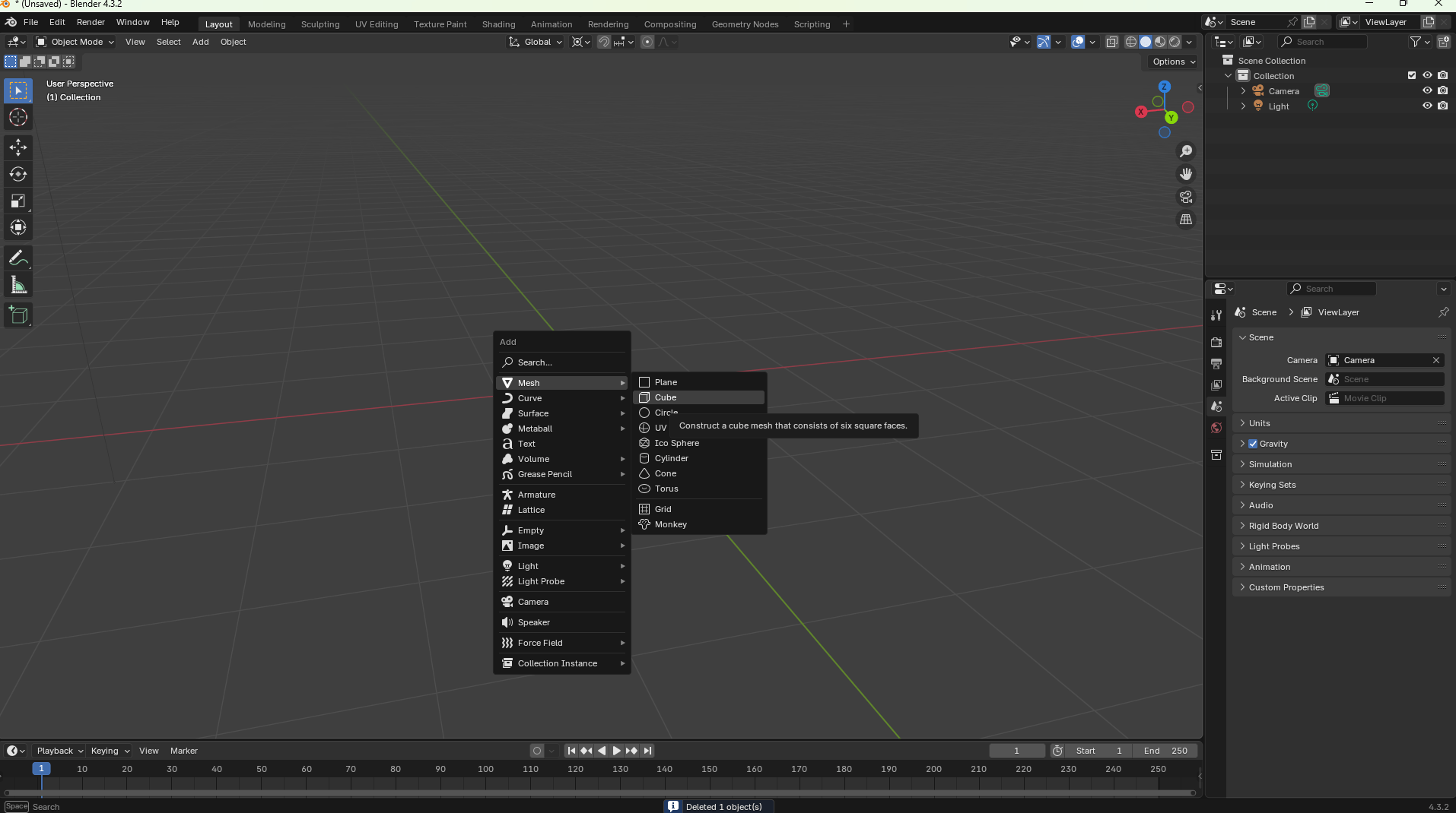
After opening the software, your screen should look like this.
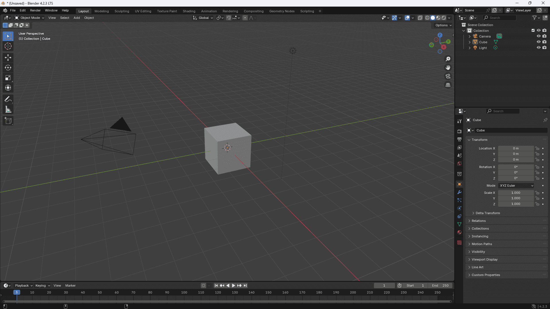
At first glance, the number of options may seem overwhelming. However, realize that you won't use everything. Blender is a powerful tool that can handle many tasks. If you focus only on asset creation, you won't need the entire software.
For camera movement, you can use the panel in the top right corner of the screen.
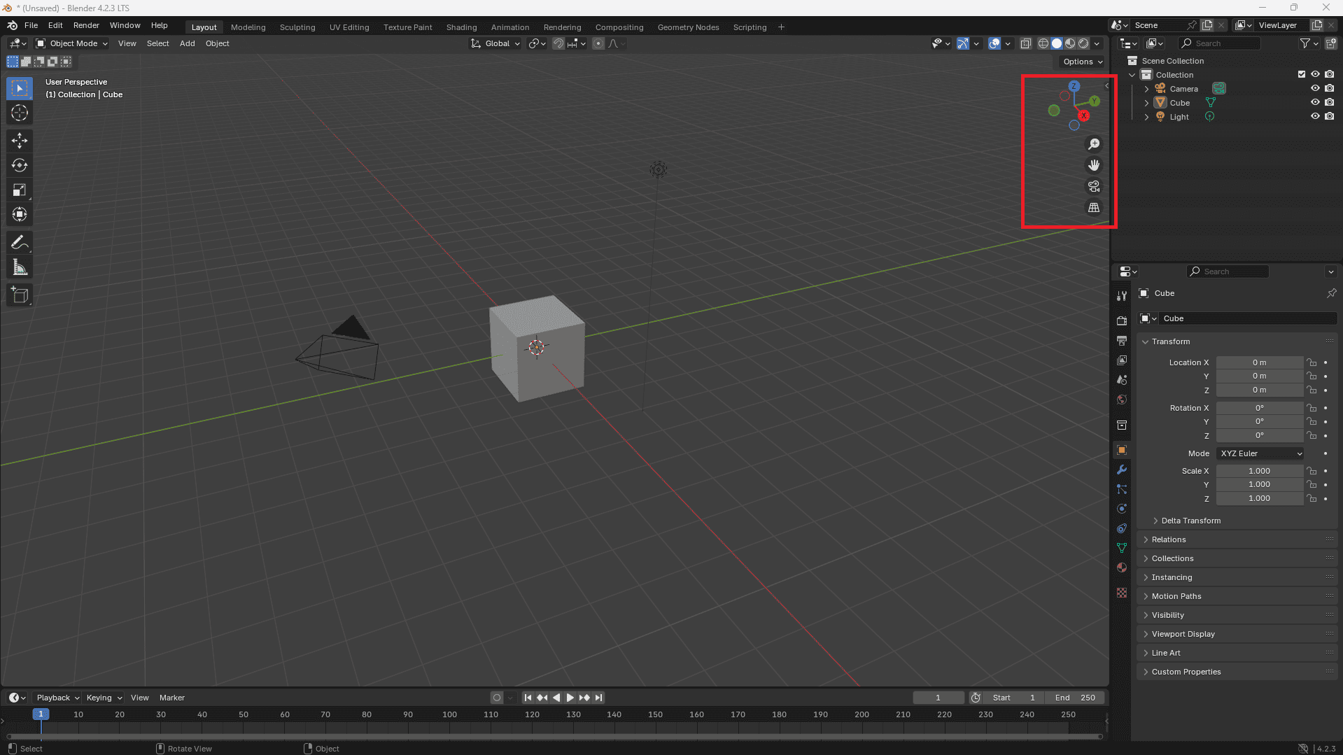
It consists of 5 elements:
- 3D manipulation widget (also known as Gizmo): allows orbital movement
- Zoom: zooms in and out of the view
- Hand: pans the display
- Toggle camera: shows camera view
Comment
Only objects visible in camera view will be rendered in the final image. You can render images in the menu panel in the top left corner or using the keyboard shortcut "F12".
- Grid projection: switches view between perspective and orthographic mode
For camera control, you can also use keyboard shortcuts:
- MMB (middle mouse button): orbital rotation of view
- Mouse wheel (Scroll): zoom in and out in fixed steps
- CTRL + MMB: smooth zoom in and out
- SHIFT + MMB: pans the display
- Numpad 0: camera view
- Numpad "." (dot): zoom to selected object (useful for setting ideal distance for rotation)
Task 2.1
Explore the interface and navigate through it.
Other useful keyboard shortcuts:
- SHIFT + A: add object or node
- G: move selected object/objects, edges, points, etc.
- S: scale selected object/objects, edges, points, etc.
- R: rotate selected object/objects...
- (G,S,R) then X/Y/Z: corresponding operation will be performed on given axis
- SHIFT + D: duplicate selected object/objects...
- H: hide selected object/objects...
- ALT + H: unhide all objects
- TAB: switch between edit and object mode
- A: select all objects in object mode, points in edit mode
- E: extrusion (pushing out) of vertices
- N: show object properties
- T: show/hide left tool panel
- CTRL + P: join objects into one - set parent
- CTRL + B: bevel edges
- CTRL + R: cut object
Comment
There are many more shortcuts. These I used most frequently when creating assets.
Task 2.2
Understanding area division in Blender.
The Blender environment consists of parts called regions.
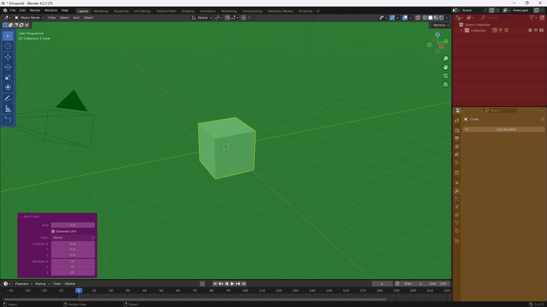
The areas we will use most frequently are highlighted in the image above.
- Main viewport (Green): This is the most prominent part of the editor, you will spend most of your time in Blender in this area.
- Tool panel (Blue): Contains a set of tools for interacting with objects.
- Last operation panel (Pink): This area appears only after adding an object and disappears after deselecting it. It serves for "final" adjustments (e.g., adding vertices).
- Scene elements (Red): Displays the hierarchy of objects located in the scene.
- Properties section (Orange): Contains various settings related to the selected object, such as color, modifiers, and others.
Comment
Keyboard shortcuts in Blender work based on the mouse cursor position. If your cursor is in the main viewport when adding a new object (SHIFT + A), it behaves as expected. However, if the cursor is over the scene elements panel and you press (SHIFT + A), instead of adding an object, the elements tree will expand or collapse.
Step 3: Creating assets! (low poly snowflake)
In this tutorial, we will show how to create a snowflake. Since there will be many of these flakes in the scene, this flake will be low-detail.
Task 3.1
Create a flake if you don't have one there.
Our flake will be a simple "+" symbol, because it will be used in large numbers and should be computationally undemanding.
Comment
You create a cube with the keyboard shortcut "Shift + A".
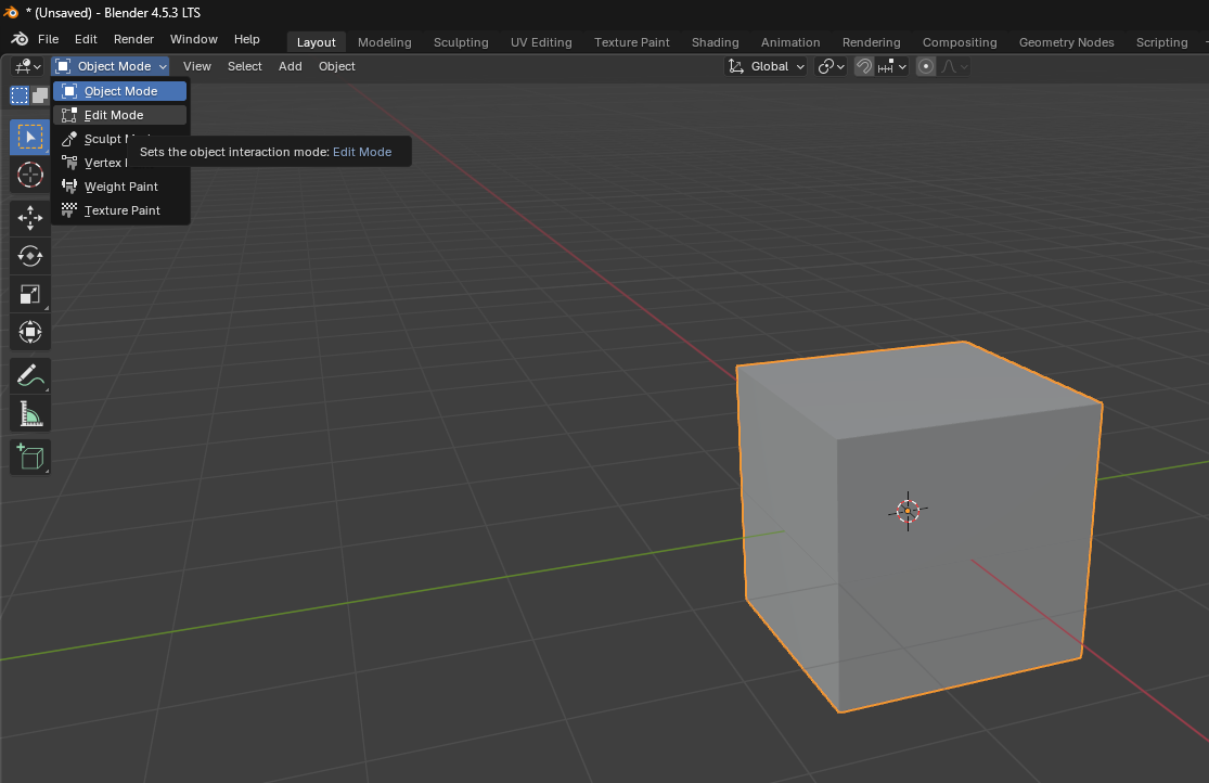
If we want to edit an object, we must select it and enter edit mode, as seen in the image, or with the "TAB" button.
Comment
The object must be selected so the tool knows which object we want to edit. Changes will then be performed on it, we cannot interact with other objects.
Then we select 4 points (vertices) on the cube and extrude them with the "E" button. We can select points by holding the "SHIFT" button and manually selecting points or by holding the left button and moving the mouse.
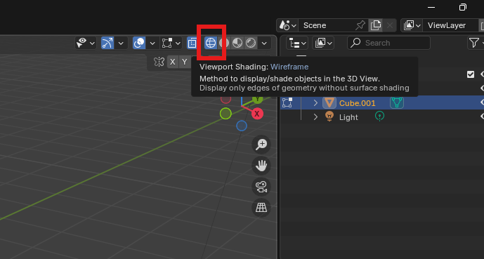
Switching to "Wireframe" view makes it easier to work with point selection.
Comment
If you accidentally selected a point you didn't want, holding the "CTRL" button and then selecting the unwanted point will cancel the selection.
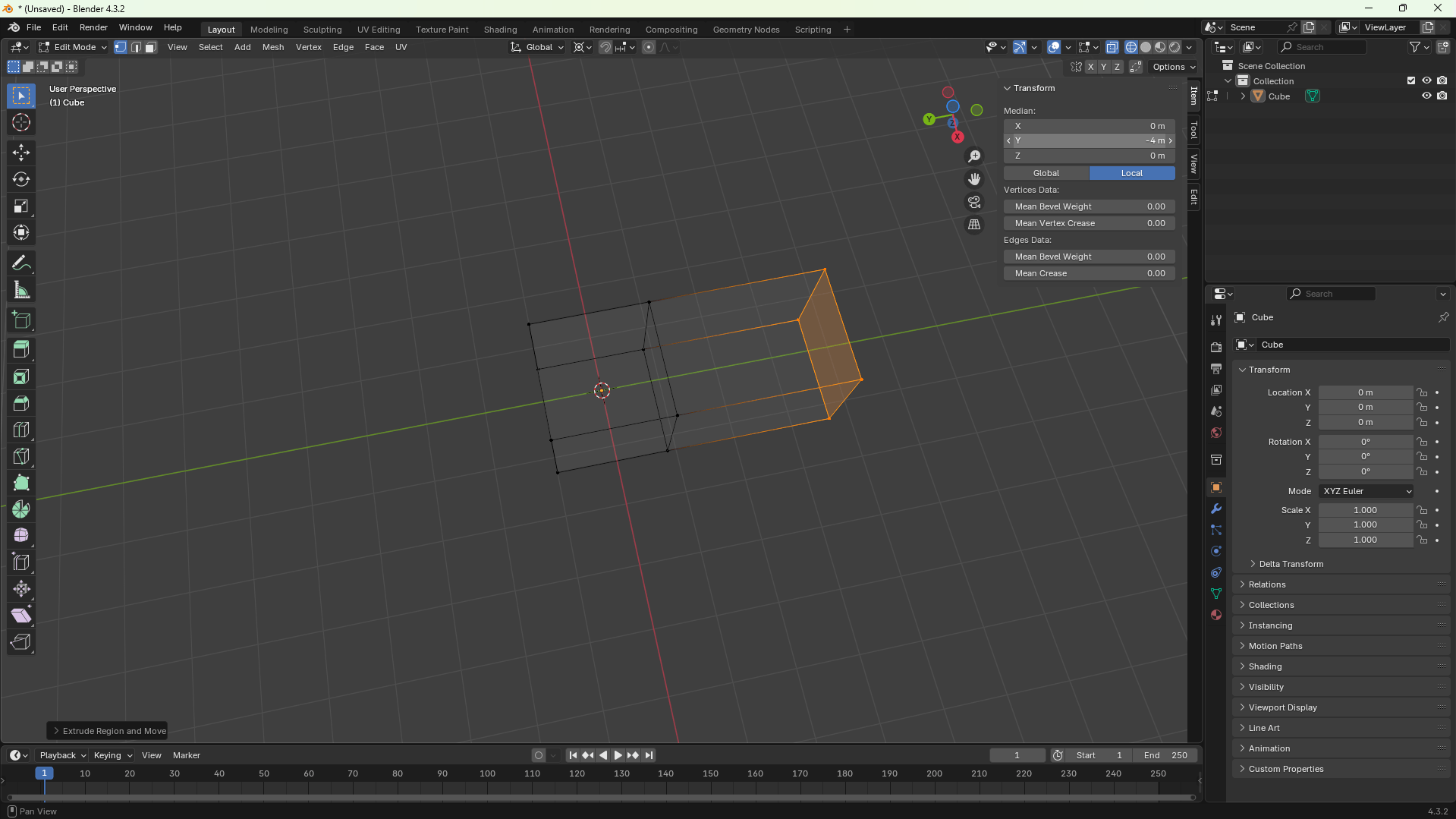
We can choose any length for each extruded shape, but each side should have the same value for the object to be symmetrical. We perform these operations in the object properties. If this window is missing, it can be displayed with the keyboard shortcut "N".
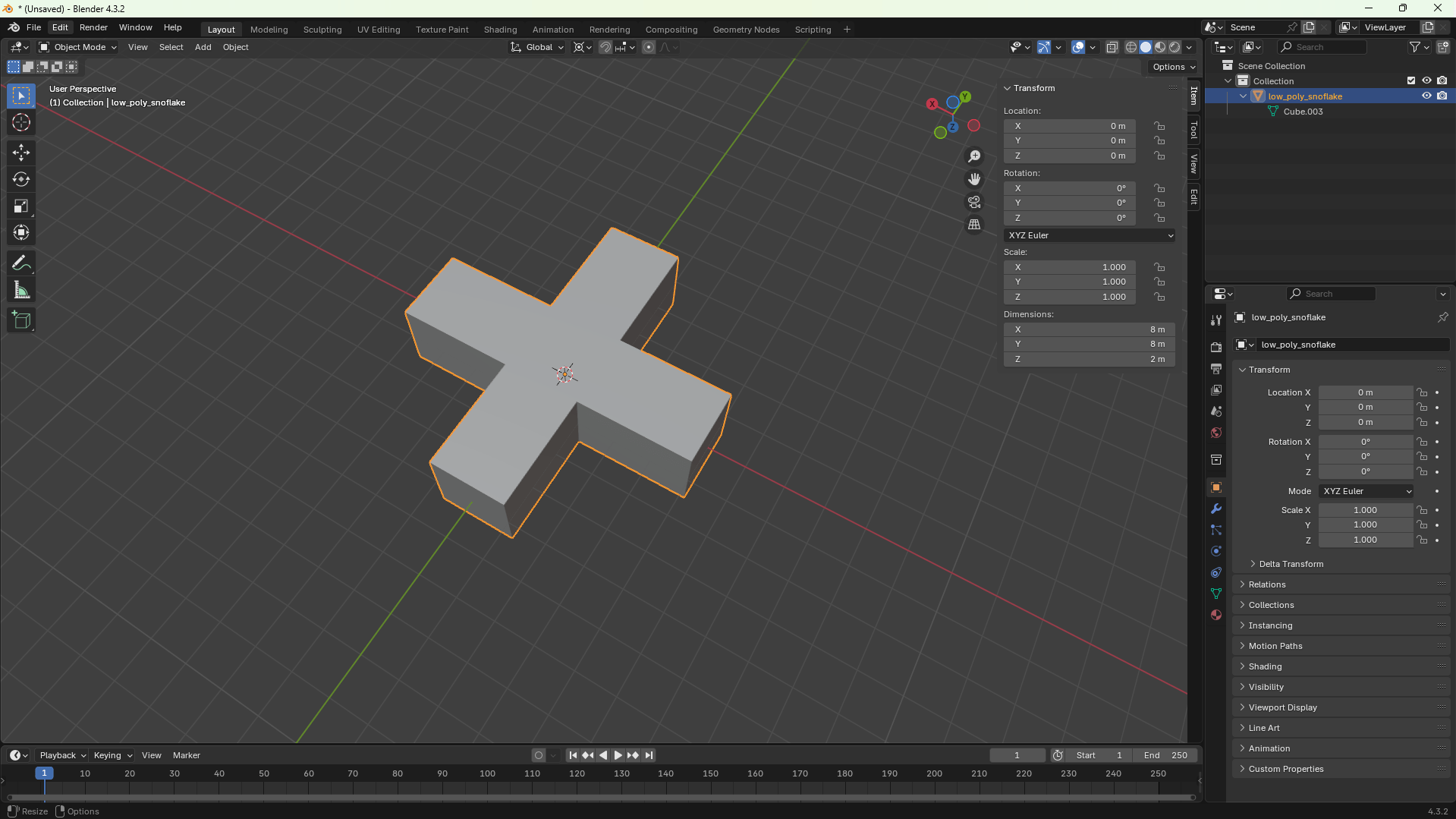
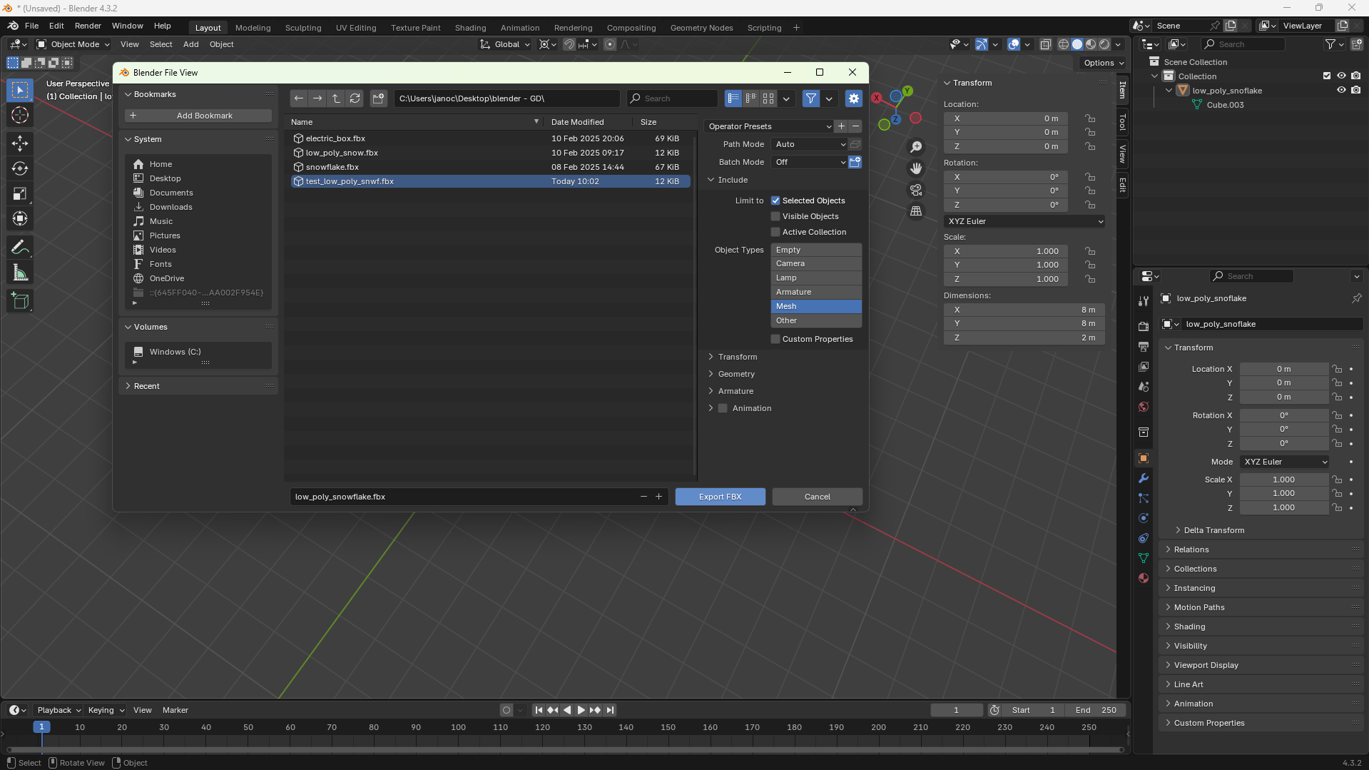
After creating the object, we can rename it in the scene elements. Before exporting, we select the object in object mode and then export the object as an FBX (from Filmbox) file. (.obj, .gltf and .glb will also work)
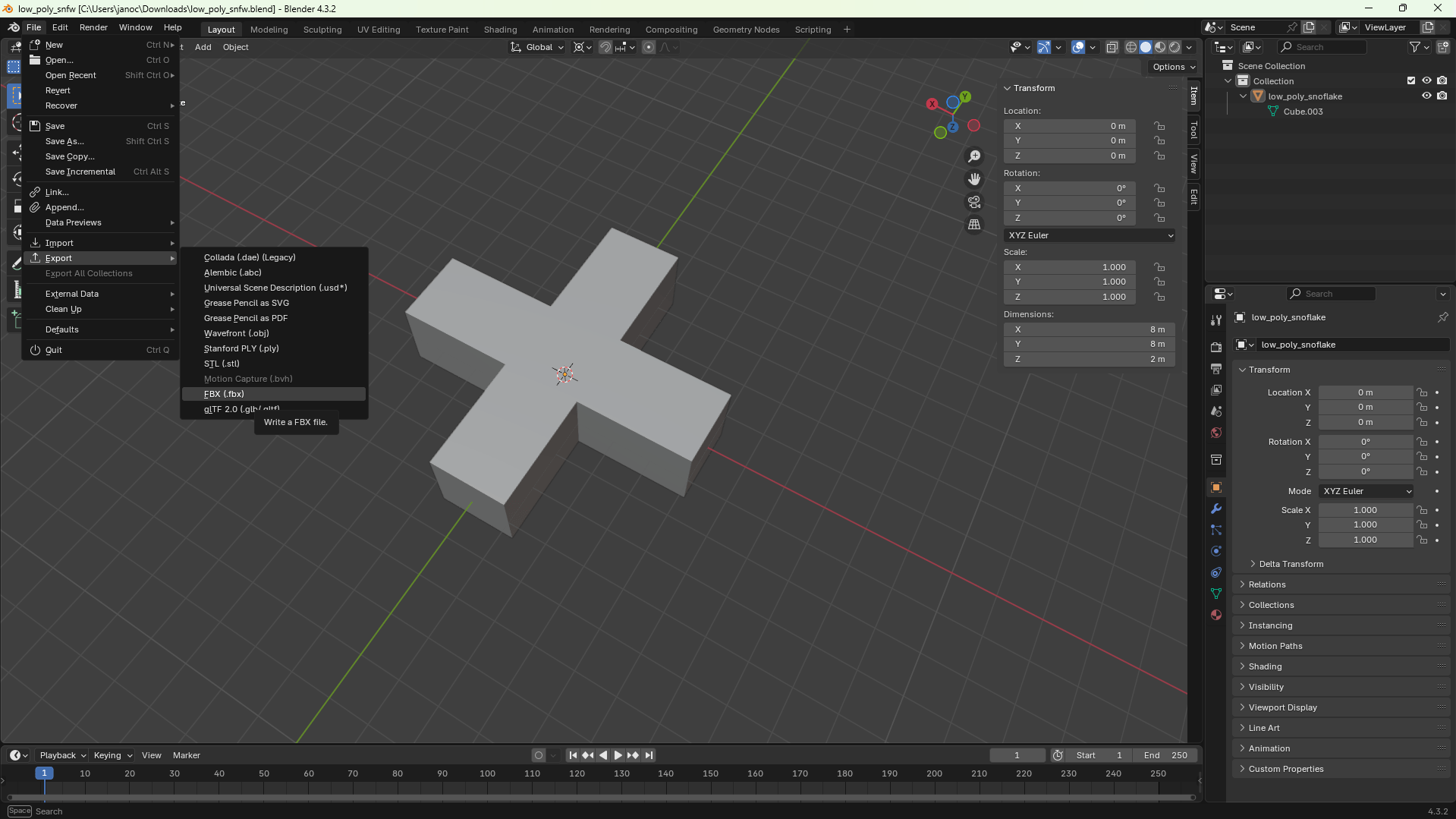
Warning
Don't forget to set the correct settings when exporting, in our case it's "Mesh" and we want to export only selected objects.
Step 4: Creating assets! (More detailed snowflake)
In this tutorial, we will show how to create a snowflake. This flake will be used near the camera, or player, which means it will be visible up close. There will be fewer flakes, so these can be more detailed.
With the keyboard shortcut "SHIFT + A" we add a new object to the scene, now we will want to work with a cylinder.
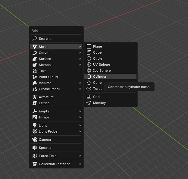
After creating the object, this window will open:
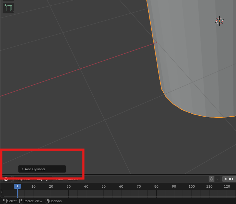
Comment
This is the last operation panel, final adjustments to the object are made in it. After clicking away from the object, this option will no longer be displayed.
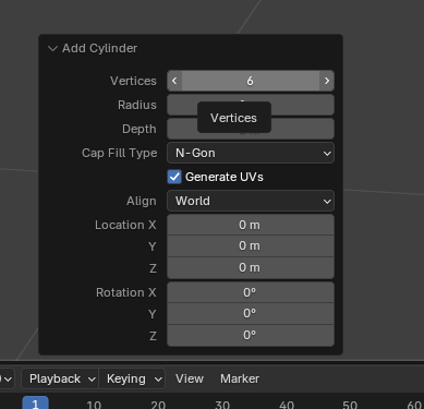
In this panel, we will adjust the cylinder edges to 6.
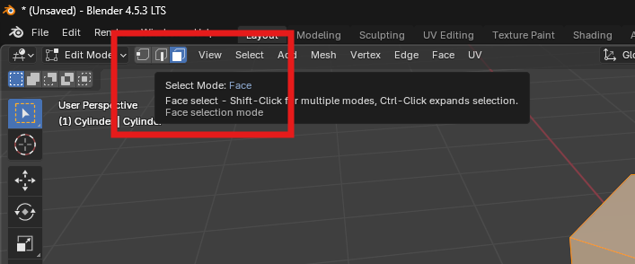
Now we will start making edit changes to the object. Again, it is necessary to enter edit mode for these modifications. In it, we will now choose the option to select faces instead of points, this will allow us to select object shapes directly instead of manually selecting points.
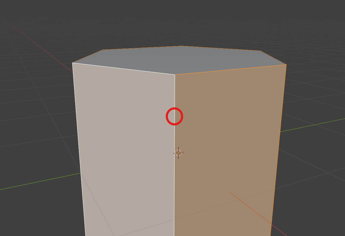
Using your mouse while holding "SHIFT" we will select the entire circumference of the cylinder.
Comment
This can also be achieved by holding "ALT + LMB" on an edge that divides the walls vertically.
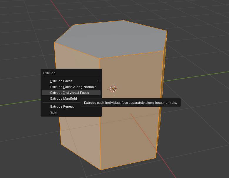
Whether you chose manual selection or automatic circumference selection, you should have the entire circumference selected. Now by pressing "ALT + E" a window with possible extrusion methods will open. We will choose the "Extrude individual faces" option. After choosing the option, we can extrude.
While we are extruding walls from the object, we can notice in the top left corner the length of how long the extruded segment is. For these purposes, try to extrude walls "2m" long.
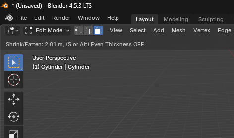
After extrusion, the object should look something like this.
Task 4.1
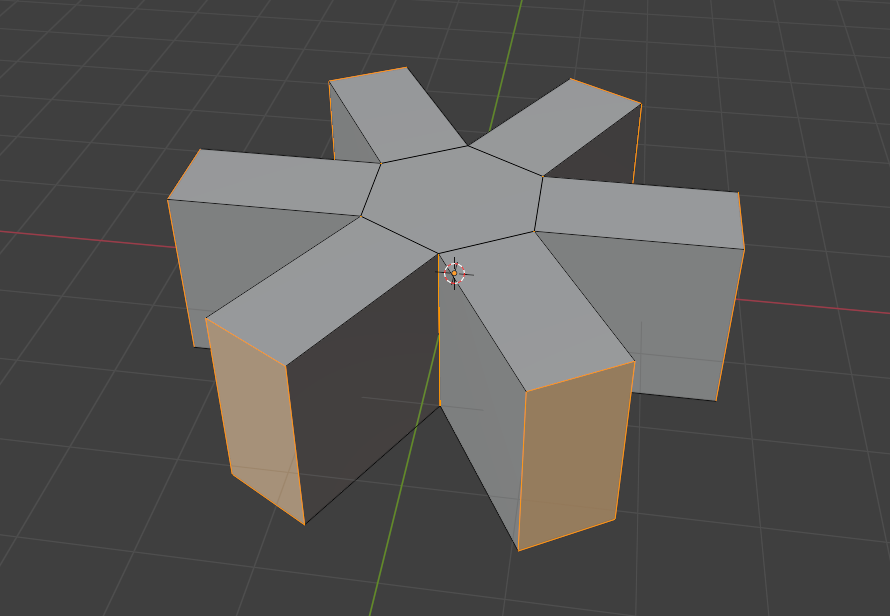
Extrude the walls 2 more times. Both extrusions should be "1m" long.
If you completed the task, you should get the following shape.
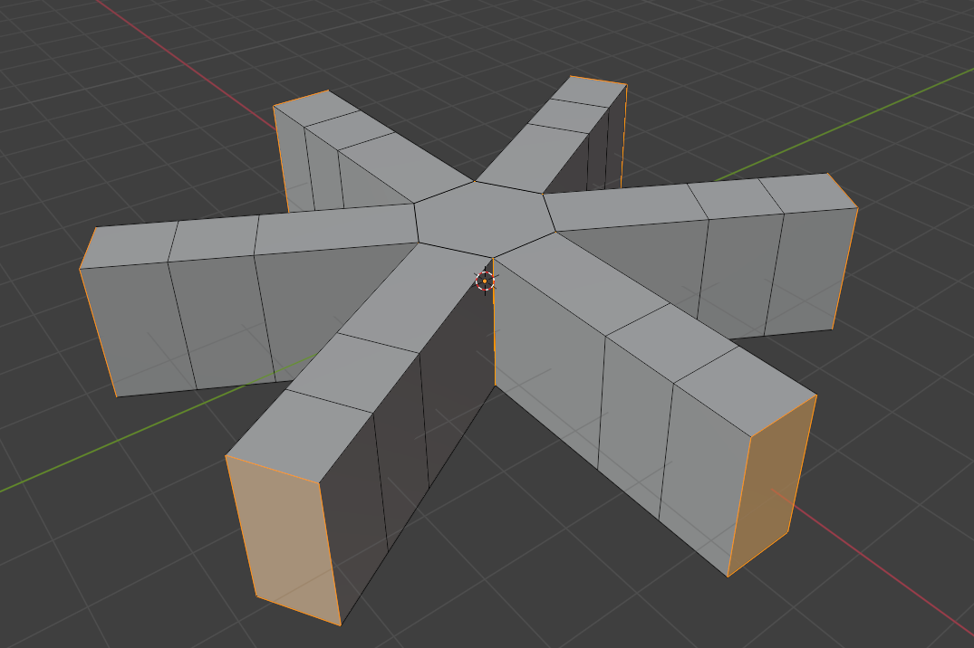
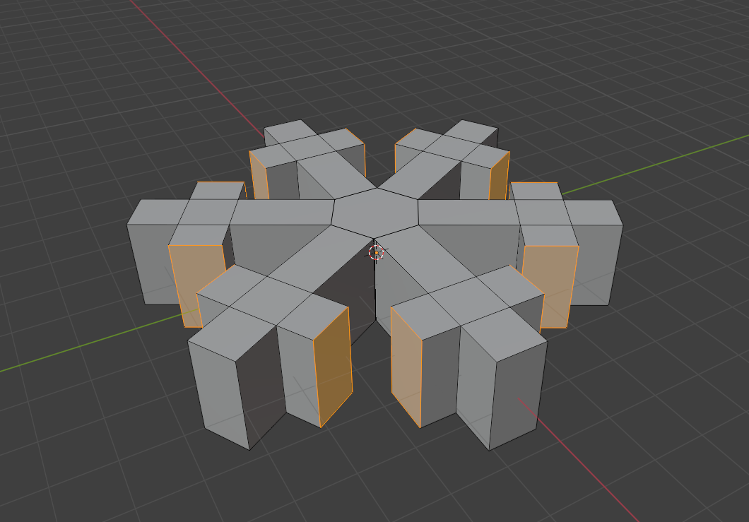
At this stage, it doesn't really represent a flake, we need to give it some "depth". We will add branches to the flake that will give it shape. At this point "ALT + LMB" won't help us, we need to select all shapes manually. By holding "SHIFT" we select all shapes in the circumference and then extrude them in the same way using "Extrude individual faces", just like in the previous steps. The edge length is arbitrary, but I chose "0.75m". At the end we should get something like this.
Now we have a flake that is more detailed, but it is very flat, it doesn't look completely finished. For a simple improvement, we can slightly modify the flake ends. We will go to the wireframe model of the flake and using the numeric keypad we can change the view to top view.
Comment
1 = Y axis
3 = X axis
7 = Z axis
9 = opposite view
Comment
If you don't have a numeric keypad, you can click on the axis in the gizmo in the top right corner. It will adjust the camera view exactly according to the corresponding axis.
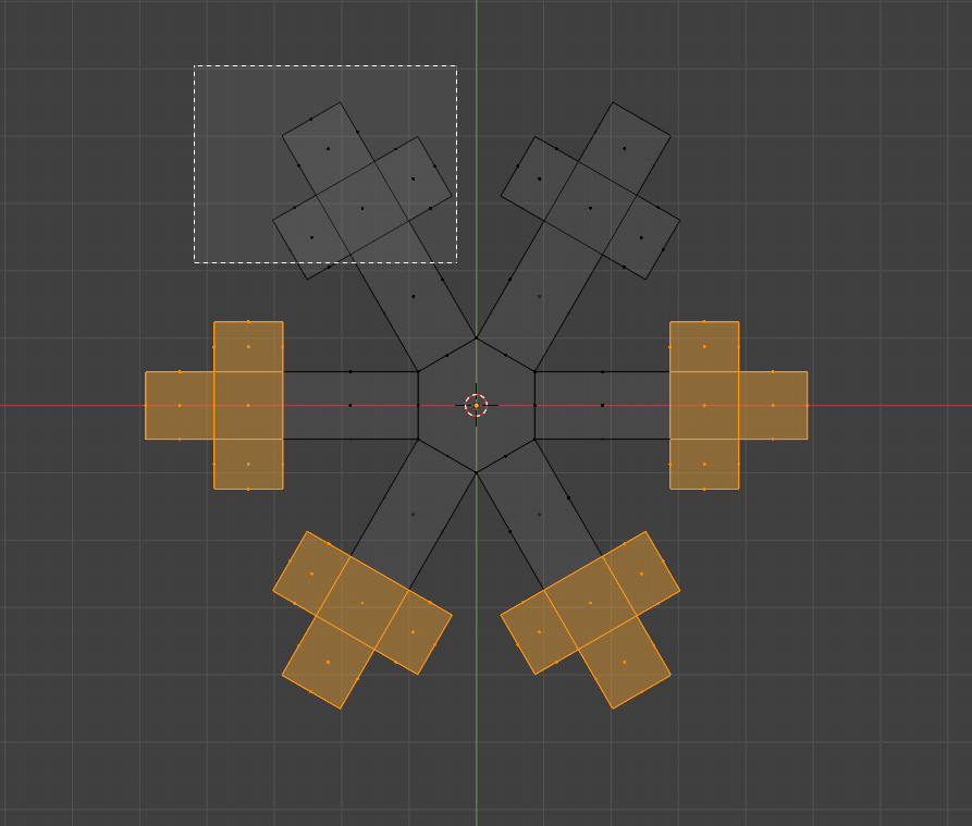
Next, we will start selecting the sides on which we will then perform the scaling function. We will select all the flake ends as shown in the image. You don't need to have the entire wall in the selection box, the dot represents what must be included for the wall to be selected.
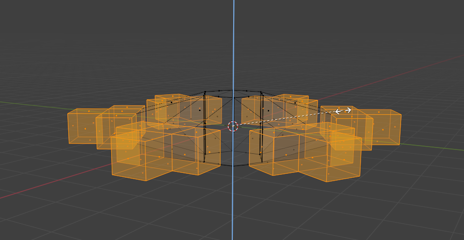
Now it's time to shrink these segments, by pressing "S + (corresponding axis X/Y/Z)" the scale change will be performed only on this axis. This is because if we didn't press the letter of the corresponding axis, the flake part would shrink in all dimensions. The image shows that the flake lies on the "Y (green)" and "X (red)" axes, so I will press "S + Z" and then scale the object parts to the desired size.
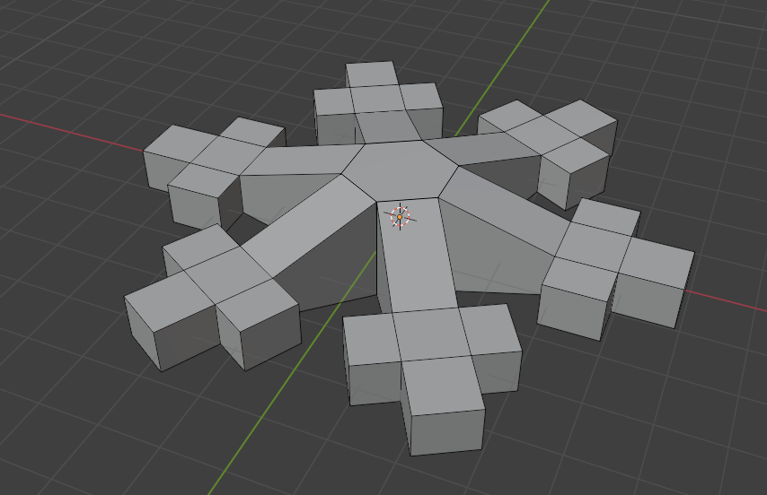
After successful scaling, we should get something like this:
If we want to add even more detail with minimal effort, we can also use "modifiers". Clicking on the modifiers button will open this window.
Comment
You need to have the flake selected.
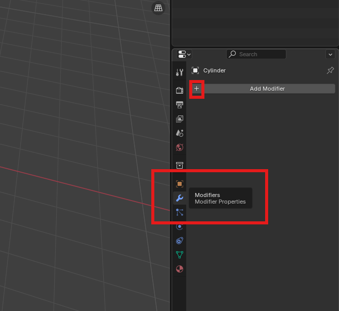
By clicking the plus I will add more modifiers, we will be interested in the modifier called "subdivision surface", which is located under "add_modifier/generate/subdivision_surface".
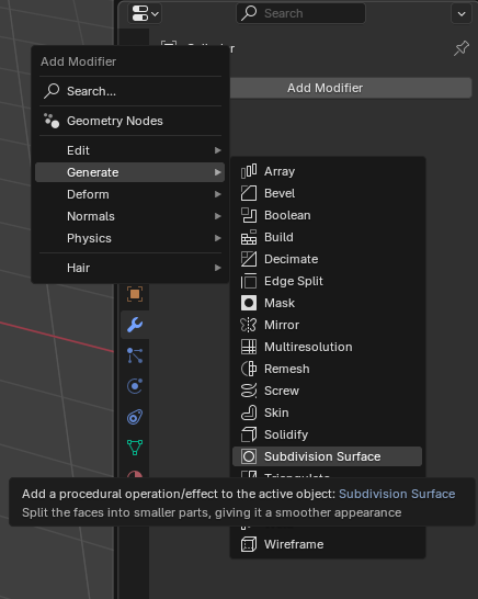
This will automatically set the modifier strength to 1, we won't need more so it won't be demanding for the computer due to the large number of polygons. Since this object will be called very quickly in the snow effect, it would accumulate.
Comment
If you want, you don't have to use the modifier at all, so you don't overload your computer too much.
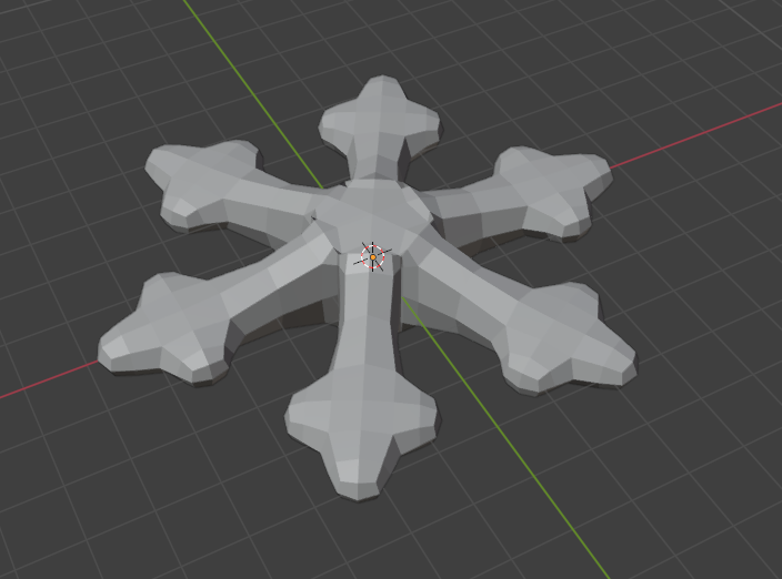
The final version should look something like this