Objectives
- Introduction to environment of the CASE System Power Designer (PD) and its basic services.
- Continuing of example project of UnIS (University Information System) - use PD for create a model of user requirements in the form of a list.
- Realisation of the requirements model using business process models (bussines process model - BPM) - use BPMN notation (Bussines Process Model Notation).
- Realization of the requirements model using use case diagram (use case diagram - USCD) - use UML notation (Unified Modeling Language).
Introduction
-
CASE systems and tools can be used for computer aided software processes throughout the lifecycle of software system from
its birth in the form of thoughts and ideas to final implementation of all service and further modifications of target system.
Computer support based on CASE tools and systems can by used by project managers (uper CASE), for analysis and design (midle
CASE) and programming, implementation work (lower CASE). Sybase Power Designer provides services mainly to support the analysis
/ design systems. Created models and related documentation are important and useful for the whole life cycle of systems.
Solution of software project starts with the collection and analysis of requirements, creating an appropriate model of requirements
which could be used for definition of internal parts of the system and external parts of surrounding of the system (external
entities) with which the system will somehow communicate.
Steps
-
PD provides a working environment for access of the project database, which stores information on the project (models, descriptions of models and their components, linkages between the models, the generated code, etc.).
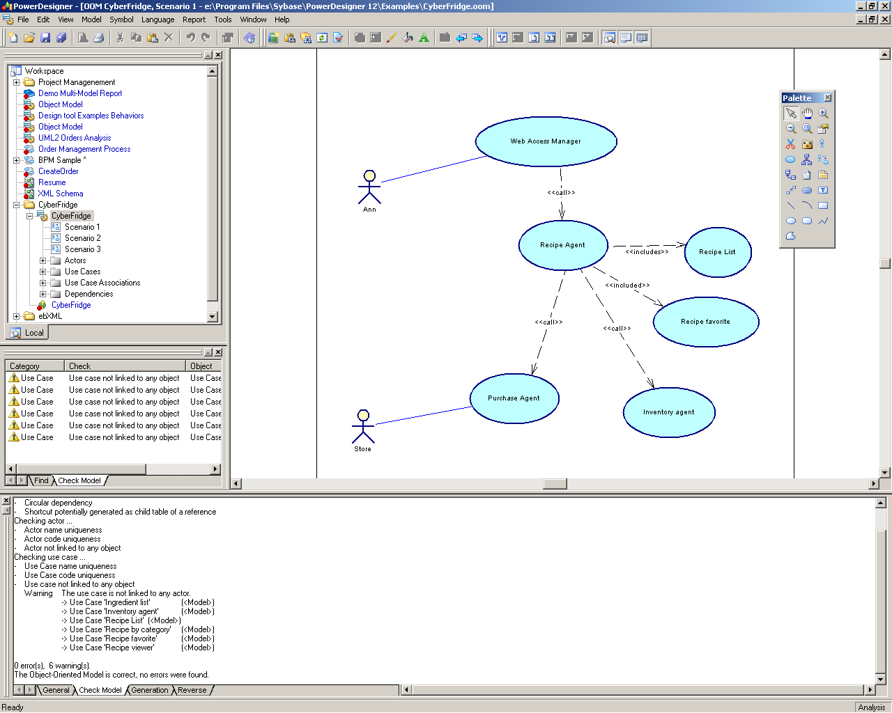 Fig.: Main screen of GUI of CASE system.Task: Open the example project from the system catalog of examples of PD. Try to explain created models and their descriptions.
 -
List of basic system requirements is an important resource for the launch of the project. This list is incrementally and iteratively actualized throughout the project and remains a useful tool in post-project stages. In the pre-project stage in project planning is the basis for a feasibility study of the project, estimates of time and cost. We can start with creating of requirement model with use of table of requirements in the PD system. For each requirement could be filled its name and a brief description. Code of requirement can stay automatically generated in early stages. Code requirements will serve to create links between requirements and other artifacts of the project. Into user-defined code can also be integrated various symptoms which can be used in sorting, browsing and zgrupovaní requirements of various important criteria.Task: Initialize the project Unis with use of PD system.Task: Create a list of basic requirements for UnIS in terms of student services.
-
System requirements can be formulated graphically in different diagrams. In the graphical representation can be achieved better clarity and clearness. The textual specification using natural language may be more detailing details in highly concentrated form. For clarity model is the best way combination of graphical representations and additional text descriptions. There are a graphical specification using charts that are linked to a precise mathematical formalism - formal specifications. Their advantage is the clarity, accuracy, and use in the generation and transformation of specifications to the required implementation. The downside is usually their complexity, less comprehensible for non-experts in IT (and thus generally unfit for use in consultation with the customer - the customer does not have to be IT specialists). An exception in this regard are graphical models of processes based on BPMN notation, which could be understandable more. http://www.bpmn.org/ The elements of these diagrams have the semantics which is clear enough for people in various application domains. Using BPMN can create business process models (BPM) suitable for requirements analysis, for creating models suitable for consultation with customers and future users of the designed system. BPM is used for the analysis of existing and development of new systems.Task: Create the BPM for selected already specified procedural requirements - requirements that relate to any service provided in terms of its performance, the necessary intermediate steps (activities), the necessary information, their sources and targets, the actors, objects and other systems. Start with definition the services necessary activities, their temporal sequence or sequence, source and destination information and stakeholders and other systems in this diagram.Task: Create description for this diagram.Task: Make presentation of drawn diagram for your colleagues and describe the model.
-
User requirements can be clearly modeled graphically in the use case diagram (USCD - use case diagram) in the language notation for object-oriented system modeling UML (Unified Modeling Language) http://www.uml.org// This diagram can also be understandable enough for expressing basic facts about modeled system: what services it will provide and to whom.Task: Create USCD for already created BPM.Task: Describe the model.Task: Compare the clarity and ability of diagrams to express modeled reality.
Resources
- PowerDesigner. Requirements Model, on-line manual.
- UML® Resource Page. Getting Started with UML: http://www.uml.org//
- Object Management Group. Business Process Model and Notation http://www.bpmn.org/